Electronics | Foreword | Basic Electronics | Complex Electronics | Electricity | Machines | History of Electronics | Appendix | edit
RLC Series
An RLC series circuit consists of a resistor, inductor, and capacitor connected in series:

By Kirchhoff's voltage law the differential equation for the circuit is:

or

Leading to:
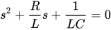
±

with
and

There are three cases to consider, each giving different circuit behavior,
\\beta^2, or \\alpha^2 < \\beta^2 "}}' id="mwJw">
.
=


Equation above has only one real root
- s = -α =
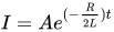
- \\beta^2"}}' id="mwOg">
\beta ^{2}}"/> ,
- 2\\sqrt{\\frac{L}{C}}"}}' id="mwPw">
2{\sqrt {\frac {L}{C}}}}"/>
Equation above has only two real roots


.

Equation above has only two complex roots


Circuit Analysis
R = 0
If R = 0 then the RLC circuit will reduce to LC series circuit . LC circuit will generate a standing wave when it operates in resonance; At Resonance the conditions rapidly convey in a steady functional method.


R = 0 ZL = ZC
If R = 0 and circuit above operates in resonance then the total impedance of the circuit is Z = R and the current is V / R
At Resonance
Or

At Frequency
- I = 0 . Capacitor opens circuit . I = 0
- I = 0 Inductor opens circuit . I = 0
Plot the three value of I at three I above we have a graph I - 0 At Resonance frequency 


Thus the circuit has the capability to select bandwidth that the circuit has a stable current when circuit operates in resonance therefore the circuit can be used as a Resonance Tuned Selected Bandwidth Filter